In iEEG/ECoG study, it is very common to localize the
electrodes using ‘CT’ scans. The CT images have different orientations
to the MR images, hence co-registration is often needed. This package
does not provide co-registration functions, as different labs might have
different approaches. threeBrain only takes co-registered
CT scans and visualize them directly. Therefore if you have already
co-registered CT, skip the next part.
The rest part of this article uses N27 sample files
mentioned by the previous vignette. If you are using this example,
please execute the following R code to set up. Alternatively, you can
substitute variables subject_code and
subject_path accordingly.
library(threeBrain)
subject_code <- "N27"
subject_path <- "~/Downloads/N27"
brain <- freesurfer_brain2(subject_path, subject_code)
CT Co-registration
(skip if you have generated co-registered CT in ‘Nifti’ formats)
This part provides one working method via dcm2niix and
FLIRT packages. Again, other methods will work as long as
they output CT aligned to MRI in ‘Nifti’ formats.
To start, please download and install dcm2niix (link),
FLIRT packages (link).
Step 1: Merge all DICOM images to
Nifti format:
Open your terminal (bash or power shell),
change directories to where CT DICOM images
are, and run
dcm2niix [folder with DICOM images]Do the same to T1 MR images too.
Step 2: Copy the two .nii files
generated in the previous step to a same folder, rename them to be
ct.nii and t1.nii
flirt -in ct.nii -ref t1.nii -out ct_in_t1.nii -omat ct2t1.mat -interp trilinear -cost mutualinfo -dof 6 -searchcost mutualinfo -searchrx -180 180 -searchry -180 180 -searchrz -180 180 There will be a ct_in_t1.nii file generated.
Localize with CT
Assuming you have generated co-registered CT scans in file
ct_in_t1.nii, please copy it to the subject folder. The
file should be located at
mri/ct_in_t1.nii
Next, type in and change the file path to ct_in_t1.nii
just created
ct_path <- file.path(subject_path, "mri/ct_in_t1.nii")
threeBrain::localization_module(subject_code = subject_code,
                                fs_path = subject_path,
                                ct_path = ct_path)
You will see the threshold CT displayed along with the pial surfaces.
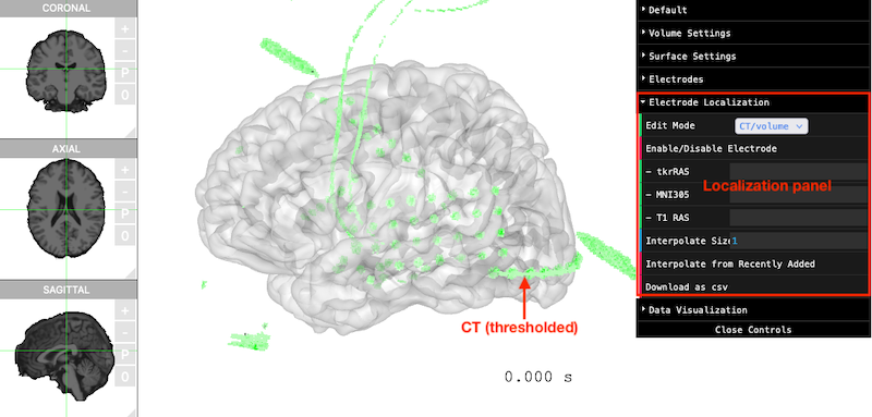
Make sure Edit Mode (in the
Electrode Localization panel) is CT/Volume.
Now move your mouse cursor to the green electrodes, the localization
control panel will display the tkrRAS
(FreeSurfer coordinate), T1 (native RAS
coordinate), and MNI305 (‘MNI’ template coordinate).
Double-click on the green areas, and a new electrode
will be created.
The default threshold of CT scans is set to 3000. However, this threshold might need to be adjusted in order to achieve high accuracy. The following figures demonstrate the results of different threshold.
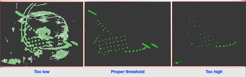
If the threshold is too low, then other irrelevant structures will appear. If the threshold is too high, some electrodes might disappear.
To adjust the CT threshold, open the Volume Settings
from the control panel, slide Voxel Min.
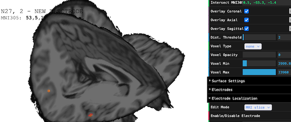
Localize with MRI (without CT)
When electrodes are too small, or the CT is unavailable, electrode localization can be done on the MR images. Localization via MRI can be done by the following steps:
- switch
Edit Mode(in theElectrode Localizationpanel) toMRI slices - open
Volume Settingspanel, enableOverlay Coronal,Overlay Axial, orOverlay Sagittal. - adjust
Coronal,Axial,Sagittalplane to desired position - double-click on the MRI slices
Automatically interpolate electrodes
In most of the scenarios, electrodes form grids or strips, The
threeBrain provides interpolation functions.
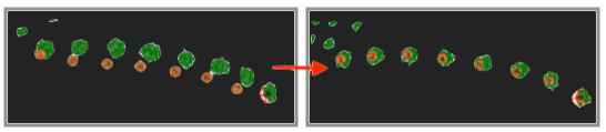
For example, we want to localize the electrodes circled in orange
color (top-left). You could of course mark them one by one. More
efficiently, you can simply localize the electrodes at both ends, set
the Interpolate Size to 6 (there are 6 more electrodes to
be added), make sure there is no other objects blocking the sight, and
hit the Interpolate from Recently Added button (circled in
the figure). All other electrodes will be automatically generated.
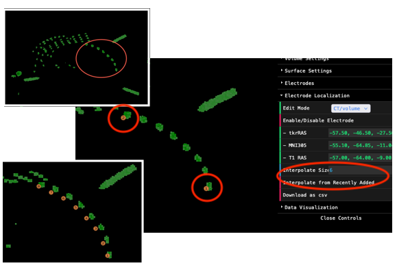
The newly added electrodes might be inaccurate. Don’t worry, you can adjust them later!
Refine electrodes
Once all the electrodes are marked, change Edit Mode to
refine. In the refine mode, you can
- Enable/Disable electrodes
- To disable/enable a particular electrode, double-click one. The
electrode will be highlighted in red color. Then click on
Enable/Disable Electrode, the electrode will be disabled/enabled. The disabled electrode will be colored in gray.
- To disable/enable a particular electrode, double-click one. The
electrode will be highlighted in red color. Then click on
- Adjust electrode locations
- Automatically adjust all electrodes
- Automatically adjust one electrode
- Manually adjust one electrode
To automatically adjust all electrodes, simply click
Auto-Adjust All. The new electrode locations will be
calculated via a weighted average.
To automatically adjust a specific electrode,
double-click one electrode. The highlighted electrode
will be colored in red. Then click on
Auto-Adjust Highlighted.
To manually adjust a electrode, double-click one
electrode. The highlighted electrode will be colored in red. Then hover
the mouse above the canvas, press and hold keyboard 1 or
shift+1 to move the electrode along Right/Left
axis. Press and hold 2 or shift+2 to move the
electrode along Anterior/Posterior axis. Press and hold
3 or shift+3 to move the electrode along
Superior/Inferior axis.
Download Electrode Table
Once Finished electrode localization, you can take screenshots by
opening Default panel, and click on
Screenshot.
To download electrode table, click on Download as csv in
the Electrode Localization panel. The electrode table
should look as follows:
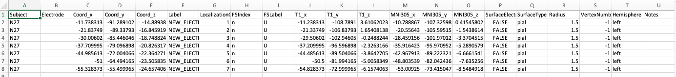
You will notice that the Electrode column is left blank.
This is because localization order might be different than the recording
channel number. Please fill out Electrode column as the
actual channel number (integers).